Properties of Directional Couplers
The properties of an ideal directional coupler are as follows.
-
All the terminations are matched to the ports.
-
When the power travels from Port 1 to Port 2, some portion of it gets coupled to Port 4 but not to Port 3.
-
As it is also a bi-directional coupler, when the power travels from Port 2 to Port 1, some portion of it gets coupled to Port 3 but not to Port 4.
-
If the power is incident through Port 3, a portion of it is coupled to Port 2, but not to Port 1.
-
If the power is incident through Port 4, a portion of it is coupled to Port 1, but not to Port 2.
-
Port 1 and 3 are decoupled as are Port 2 and Port 4.
Ideally, the output of Port 3 should be zero. However, practically, a small amount of power called back power is observed at Port 3. The following figure indicates the power flow in a directional coupler.

Where
-
PiPi = Incident power at Port 1
-
PrPr = Received power at Port 2
-
PfPf = Forward coupled power at Port 4
-
PbPb = Back power at Port 3
Following are the parameters used to define the performance of a directional coupler.
Coupling Factor CC
The Coupling factor of a directional coupler is the ratio of incident power to the forward power, measured in dB.
Directivity DD
The Directivity of a directional coupler is the ratio of forward power to the back power, measured in dB.
Isolation
It defines the directive properties of a directional coupler. It is the ratio of incident power to the back power, measured in dB.
Isolation in dB = Coupling factor + Directivity
Two-Hole Directional Coupler
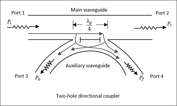
This is a directional coupler with same main and auxiliary waveguides, but with two small holes that are common between them. These holes are λg/4λg/4 distance apart where λg is the guide wavelength. The following figure shows the image of a two-hole directional coupler.

A two-hole directional coupler is designed to meet the ideal requirement of directional coupler, which is to avoid back power. Some of the power while travelling between Port 1 and Port 2, escapes through the holes 1 and 2.
-
 2.2-2.4GHz 30dB Directional Coupler
 -
 2-18GHz 6dB Directional Coupler
 -
 2-2.5GHz 50dB Directional Coupler
 -
 26-31GHz 10dB Directional Coupler
 -
 17-22GHz 10dB Directional Coupler
 -
 12-18GHz 6dB Directional Coupler
 -
 0.5-40GHz 20dB Directional Coupler
 -
 0.5-3GHz 10dB Directional Coupler
 -
 25.5-2.7GHz 20dB Directional Coupler
 -
 5.8-8.4GHz 10dB Directional Coupler
 -
 4-18GHz 20dB Directional Coupler
 -
 2.2-2.3GHz 10dB Directional Coupler

